Tutorial 5 of 6
SPICE netlists, export and convergence troubleshooting
Advanced 15 min
Import a SPICE netlist, export a schematic to ngspice or LTspice, and read Ohmforge's plain-language diagnostics when a circuit has no solution or will not converge.
Ohmforge speaks a practical subset of SPICE, the text format almost every circuit simulator understands. You can paste circuits from textbooks and forums, and you can take your schematic to ngspice or LTspice when you need more.
1. What the importer understands
| Line | Meaning |
|---|---|
R C L | resistor, capacitor, inductor (IC= sets the initial condition used with UIC) |
V I | voltage and current sources: DC, AC mag phase, SIN(…), PULSE(…), PWL(…) |
D Q M | diode, BJT (NPN/PNP), MOSFET (NMOS/PMOS) with .model lines or built-in models |
E G | voltage- and current-controlled sources |
K | coupling between two inductors (transformers) |
.model | D, NPN, PNP, NMOS, PMOS parameters |
.op .dc .ac .tran | analyses (.tran … UIC supported) |
Values take the usual suffixes: f p n u m k meg g t. 1k, 4.7u and 10meg all work, and a trailing unit such as 10kOhm is ignored. Node 0 is ground. Built-in model names include 1N4148, 1N4007, 1N5819, BAT54, 2N3904, 2N3906, BC547B, BC557B, TIP31C, TIP32C, 2N7000, BS250, IRLZ44N, IRF9540, and LED_RED, LED_GREEN, LED_BLUE, LED_WHITE and so on. A built-in part keeps its ratings, so an overdriven LED_RED from a netlist is flagged as burnt just like a placed one.
2. Import a netlist
Choose File → Import SPICE netlist… (or Paste a SPICE netlist on the start screen) and paste:
* Diode clipper
V1 in 0 SIN(0 5 1k)
R1 in out 1k
D1 out 0 1N4148
D2 0 out 1N4148
.tran 5u 3m
.end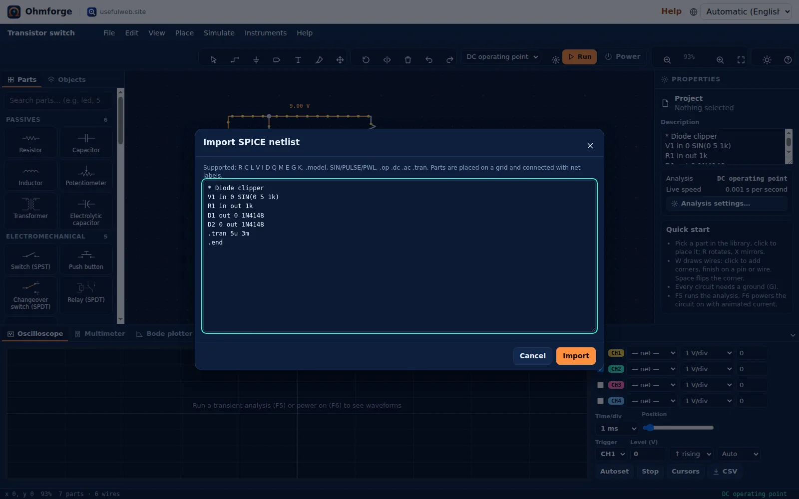
Ohmforge creates a schematic. Every element gets its symbol, and the nodes are joined with net labels: two labels with the same name are connected. The .tran line becomes the project's transient setting, so F5 runs it immediately. You can also open .cir, .sp and .net files directly with Ctrl+O.
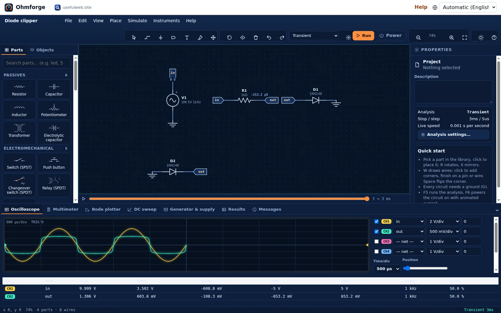
The two anti-parallel 1N4148s clip the 10 V pp input at about ±0.65 V. Ohmforge's transient tool returns min −0.65323, max 0.653225 for V(out). Drag the parts into a tidier layout if you want. The connections stay intact, because they belong to the labels, not to the positions.
Lines the importer doesn't support are rejected with their line number, so nothing is silently dropped. For example, a subcircuit call:
Line 4: element "X1" is not supported (supported: R C L V I D Q M E G K)3. Export to SPICE
File → Export… → SPICE netlist (.cir) writes a netlist for ngspice, LTspice or any other SPICE. For the Transistor switch template it produces:
* Transistor switch
* Exported by Ohmforge (usefulweb.site). Behavioural parts are approximated, see comments.
V1 N001 0 DC 9
* SW1: switch exported as a resistor in its current state (closed)
RSW1 N001 N002 10m
R1 N002 N003 10k
R3 N003 0 100k
R2 N001 N004 470
D1 N004 N005 M_D_1
Q1 N005 N003 0 2N3904
.model M_D_1 D(IS=2.1994e-19 N=2 RS=4 BV=5 IBV=10u CJO=30p)
.model 2N3904 NPN(IS=6.734f BF=416.4 BR=737.1m VAF=74.03 CJE=4.5p CJC=3.6p)
.end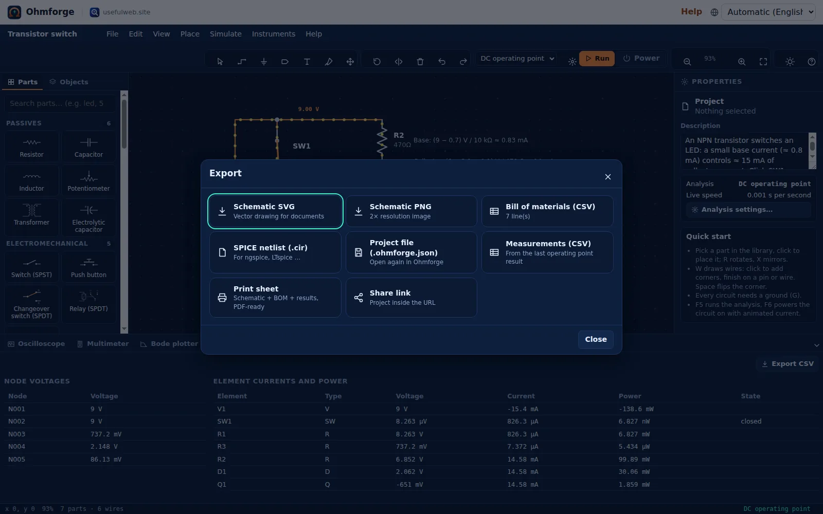
The netlist survives a round trip. Fed back into the DC operating-point tool, it gives the same 14.58 mA collector current and 737.2 mV base voltage as the schematic. Switches export as resistors in their present state, and the LED becomes a diode model fitted to its colour. Parts with no SPICE equivalent (555, logic gates, comparators, bench instruments) are written as comments that explain what is missing. Simulate → Show SPICE netlist… shows the same text without saving a file.
4. When there is no solution
Most failed simulations come from the circuit, not from the solver. Ohmforge checks the topology before it solves anything, and it explains the problem in Messages. Show buttons there select the culprit.
| Message (shortened) | Cause | Fix |
|---|---|---|
| V2 closes a loop of voltage sources and/or inductors between a and 0 | two ideal sources in parallel, a source shorted by a wire, an inductor across a source | add a small series resistance or remove the short |
| Nothing is connected to ground (node 0) | no ground symbol | add a ground (G) to the negative side of the supply |
| No DC path to ground from c | a node reached only through capacitors or current sources | add a large resistor (e.g. 10 MΩ) to ground. Ohmforge ties the node to 0 V with a tiny gmin conductance meanwhile |
| Node X has no defined voltage (singular matrix) | a floating section | connect it, or ground it through a resistor |
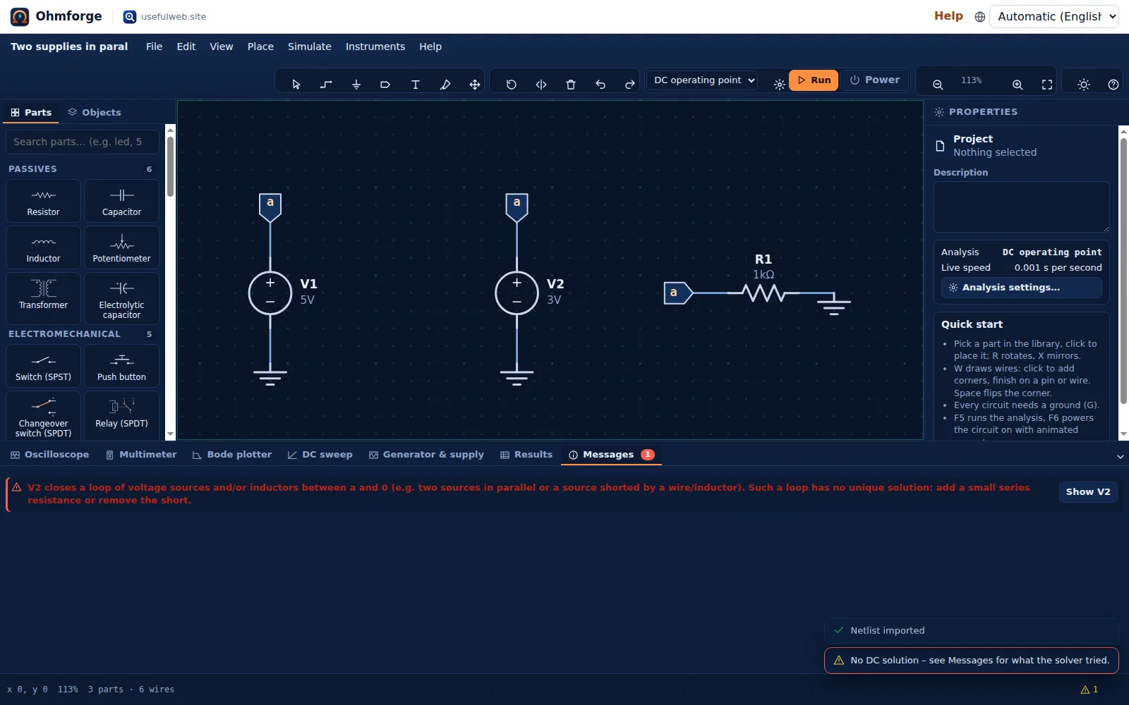
The same check runs in the API. This netlist
* two sources in parallel
V1 a 0 5
V2 a 0 3
R1 a 0 1k
.op
.end
returns "converged": false with:
V2 closes a loop of voltage sources and/or inductors between a and 0 (e.g. two sources in parallel or a source shorted by a wire/inductor). Such a loop has no unique solution: add a small series resistance or remove the short.
5. When the solver doesn't converge
Nonlinear circuits are solved with Newton–Raphson iterations. When plain Newton doesn't settle, Ohmforge escalates automatically, in this order:
- Damped Newton: each iteration may change a node by at most 0.5 V.
- gmin stepping: a conductance from every node to ground, stepped from 10⁻² S down to 10⁻¹² S.
- Source stepping: all sources ramped from 0 to 100 %.
The result reports which strategy succeeded ("strategy": "Newton–Raphson" in the API). If every strategy fails, the diagnostics list what each attempt did and name the node or current that wouldn't settle ("Newton–Raphson did not settle: the voltage at node … kept jumping between … V and … V"). Positive feedback without hysteresis (latches, Schmitt triggers built from ideal parts) is the usual cause.
For transient runs:
- "Time step too small at t = …" means the step shrank below the minimum at a sharp edge. Switch Integration to Backward Euler (more damped than trapezoidal), add a little series resistance to switches and sources, or lower the output step.
- Ringing that doesn't belong in the circuit, right after a sharp edge, is a typical trapezoidal artefact. Backward Euler damps it.
- Oscillators (555 astables, ring oscillators, multivibrators) have no stable DC state. Use UIC ("Start from initial conditions") so the run doesn't depend on an operating point that doesn't exist.
- Very long runs are capped at 20 000 output samples and a step limit. The message tells you to increase the step or shorten the stop time.
6. Compatibility limits
- No subcircuits:
.subcktandXlines are rejected, so flatten the netlist first. There are no behaviouralBsources and no temperature sweeps either. .include,.lib,.param,.options,.ic,.temp,.measand the print/plot lines are skipped, each with a warning ("Line 3: .lib is ignored by Ohmforge."). Unknown control lines are skipped the same way.- Model parameters outside the level-1 MOSFET and Ebers–Moll BJT sets (e.g.
XTI,KF) are ignored silently, so check.modellines from vendor libraries. - LTspice netlists usually import once their
X…subcircuit lines are replaced with plain parts.