Tutorial 1 of 6
Your first circuit in 5 minutes
Beginner 5 min
Light an LED through a series resistor, power the circuit on, read the current on the multimeter and see what happens when the resistor is too small.
Ohmforge runs entirely in your browser. You don't install anything or create an account, and your circuit autosaves in this browser while you work ("Saved locally" in the status bar).
1. Open the start screen
When you launch Ohmforge for the first time, the start screen opens. You can get back to it at any time with File → Start screen & templates… (Ctrl+N). It offers three ways in: a blank circuit, a file you open, or a pasted SPICE netlist. Below them are 13 templates and the projects you've worked on recently.

Choose LED with series resistor. The circuit is the classic first one: a 9 V battery (BT1), a switch (SW1), a 390 Ω resistor (R1) and a red LED (D1).
2. Find your way around
- Left: the part library (Parts) and a list of everything in the circuit (Objects). Type in the search box (
led,555,npn…) to find a part. - Middle: the schematic. Scroll to zoom, drag the empty background to pan, and press
Fto fit the circuit to the window. - Right: the Properties inspector for the selected part. With nothing selected it shows the project and its analysis settings.
- Bottom: the instruments: oscilloscope, multimeter, Bode plotter, DC sweep, generator and supply panels, the results table and the messages.
3. Power it on
Click Power in the toolbar (or press F6). The circuit now runs as a live simulation:
- yellow dots move along the wires in the direction of conventional current,
- wires take on a colour that shows their voltage,
- the LED lights up, and its brightness follows its current.
Open the Multimeter tab, choose A and pick D1 as the element. The meter reads about 18.2 mA.
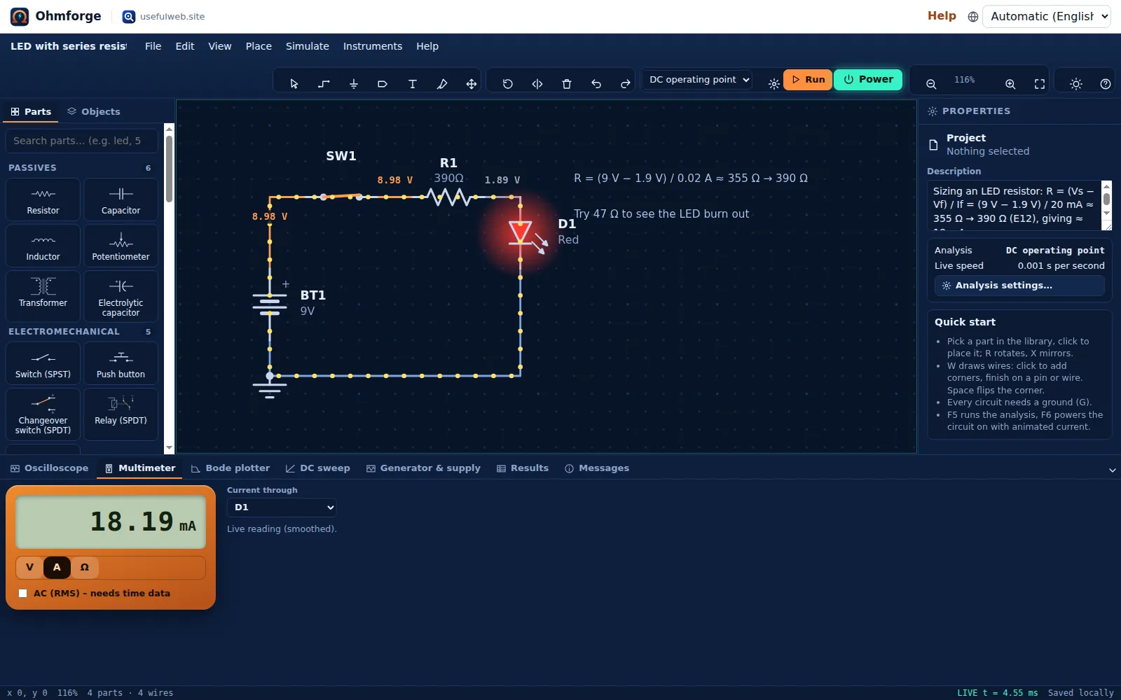
Here is where that number comes from. The red LED drops about 1.9 V, so the resistor sees 9 V − 1.9 V = 7.1 V, and 7.1 V / 390 Ω ≈ 18.2 mA. The datasheet's 20 mA would need 355 Ω, which is not a standard value. 390 Ω is the next E12 value up, and it keeps the current safely below 20 mA.
Click SW1 on the schematic while the circuit runs. The switch opens and the LED goes dark. Click it again to close it.
4. Break it on purpose
Click R1. In the inspector, change Resistance to 47 and press Enter. While the power is still on:
- The current jumps to about 136 mA, nearly seven times the LED's 20 mA rating.
- The LED is drawn burnt out: a red cross over the symbol and a red frame around it.
- The inspector shows a stress warning: "136.1 mA through the LED is far above its 20 mA limit – a real LED would burn out. Add or increase the series resistor."
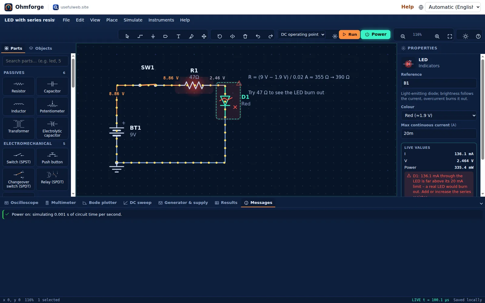
Resistors, diodes, transistors, capacitors (voltage), inductors and fuses all carry ratings like this. Ohmforge checks the simulated values against those ratings in every analysis.
Press Ctrl+Z to undo the change, and the LED works again.
5. Run a DC operating point
Turn the power off (F6). Make sure the toolbar's analysis selector says DC operating point and press Run (F5). The Results tab lists every node voltage, and the current and power of every element. Voltage tags also appear on the schematic.
6. Save and share
Ctrl+Ssaves an.ohmforge.jsonfile you can open again later. Autosave keeps a copy in this browser either way.- File → Share link… packs the whole project into a URL, so the person you send it to doesn't need an account.
- File → Export… (
Ctrl+E) writes SVG/PNG schematics, a SPICE netlist, a bill of materials and the measured values as CSV.
Do the same calculation without the app
The calculator tool Ohmforge LED Resistor Calculator does steps 3 and 4 in one go. It computes the exact value, rounds it up to the E-series, and then simulates the circuit with the same LED model:
Use 390 Ω (E12, ≥ 0.5 W): 1× red LED on 9 V draws 18.24 mA (exact value 355 Ω).
It reports 18.24 mA instead of the 18.19 mA the meter showed, because the template's battery has 1 Ω of internal resistance and the calculator assumes an ideal 9 V supply.